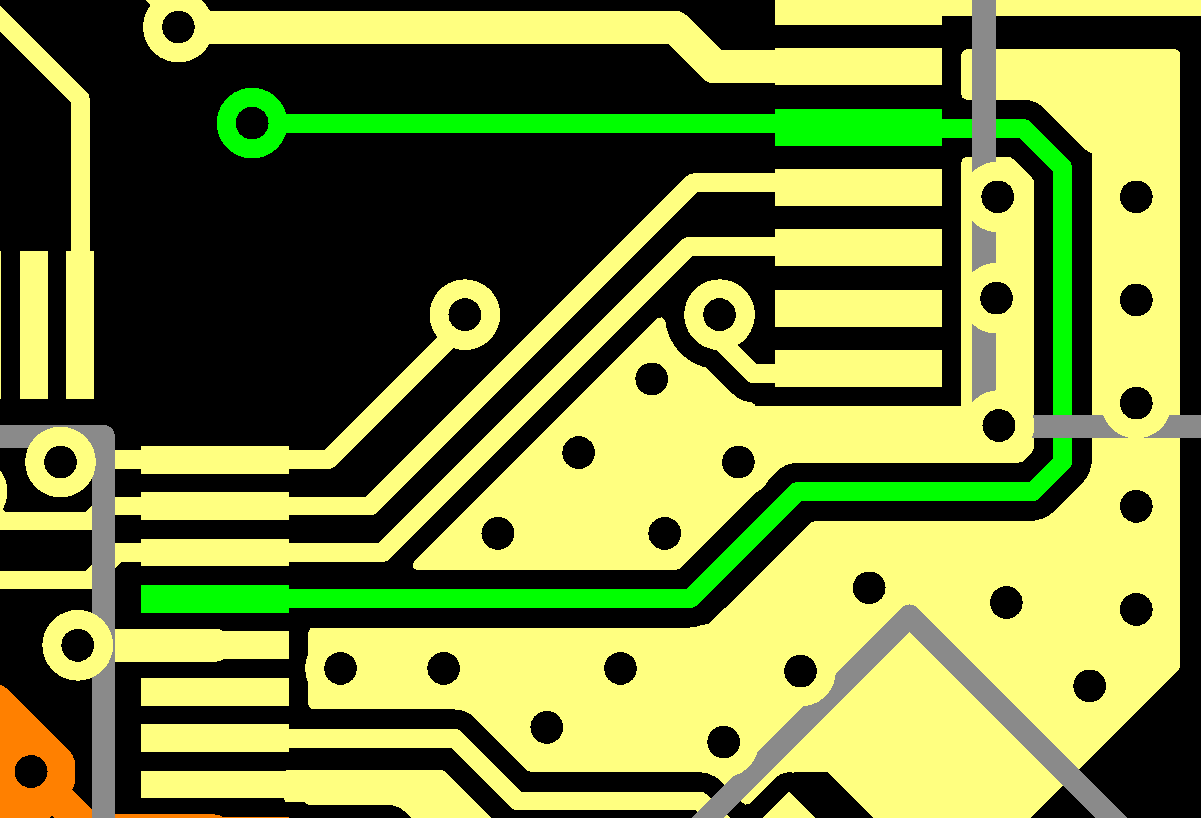

This annex provides a general overview of circuit board design considerations for numerous electronics measurements, not just inductance. Ideally the reference trace should terminate in the same type of pad or connection as the actual connector would experience.Ĭ Printed circuit board design considerations for electronics measurements (informative)

This is appropriate for pin-in-hole terminations, but is not appropriate for all terminations, e.g. NOTE 2 The calibration structures above are described as terminating in a via. NOTE 1 This reference structure should be designed with the same configuration in which the specimen would be used in a typical application (such as footprint pads, grounds, traces, vias, etc). The test fixture shall provide an identical coaxial cable or probe connection at both ends. The length of this reference trace should be the same as that of the trace connected to the near end of the specimen.ī.2.4 A reference structure consisting of a through transmission trace whose length is equal to the total fixture trace length for a single path, (length of the near end and far end traces). The length of this reference trace should be the same as that of the trace connected to the near end of the specimen.ī.2.3 A reference trace terminated in the specimen environment impedance.

The length of this reference trace should be the same as that of the trace connected to the near end of the specimen.ī.2.2 A reference trace ending in a via which is open with respect to the return path conductor(s). Recommended test fixture configurations include:ī.2.1 A reference trace ending in a via which is shorted to the return path conductor(s). Test boards shall include reference traces for measuring the frequency domain characteristics of the fixture in order to correct for fixture effects (e.g., discontinuities in impedance).


 0 kommentar(er)
